Wednesday, August 28, 2013

Tube amp improvements: some measurements (part 4)

After assembly the tube audio amplifier, I have got some measurements to plot the frequency response magnitude.
I have used a 8ohms purely restrictive load (figure below).


I swept the frequency of an sinusoid input signal from 20Hz to 20kHz. I took the outputs signals in an oscilloscope Tektronix Type 422.
Bass and treble adjust were on the maximum position.
Figure below shows the frequency response magnitude.


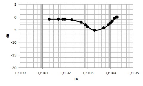
I haven't noted any distortion. Even in low frequencies, the output sinusoid is free of distortion.
Figures below shows outputs at 20Hz, 30Hz, 50Hz and 80Hz.


Following my propose (previously posted: tube amp improvements part 1):

1) Big output transformers (high inductance) provide a good response at low frequencies and without distortions.
2) I can't evaluate yet the benefits of bigger power source capacitors. I have not seen ripple at output. I can hear a humm noise but the circuit in not shielded yet. After I conclude the shield I will can evaluated the benefits of bigger capacitors.
3) I tried bigger coupling capacitors and also eliminated them in some connections, but I have not noted significant results for the bandwidth.
4) The next step will be: tests with output transformers at ultralinear configuration. I will connect the screen resistors to the specific wires of the output transformers primaries.

My first impressions: very good output transformers and tubes (Sylvania).

Monday, August 26, 2013

Tube amp improvements: output transformers (part 3)

Figures below show my two new output transformers (one per channel).

At the primary there are the wires for five connections: +B, two plates (push pull) and the two screens.
At the secondary there are wires for connections to speakers with 8ohms or 4ohms.

They were designed for 5000ohms plate-to-plate effective load resistance, 250VDC plate voltage (+B to plate) and 20Wrms.

The magnetization inductance need be sufficient to get a bandwidth from 20 to 20kHz. This inductance is parallel to the reflected load. Then, roughly, the cut-off frequency will be:

fc = R/(2*pi*L)
L = R/(2*pi*fc)

It can be seen that the size of the output transformer limits the low frequencies response. To get deep bass it is necessary high inductance:

L = 5000/(2*pi*20) = 40 H

Briefly, that is why I got big output transformers (40H!!!).

Firstly I will not use the screen grid connections. I will do some tests and get some measurements. After, I will connect the screen grids wires and compare the results.

Figures below shows the source power transformer. At the secondary there are connections to the filaments of the tubes (6.3V AC) and to the rectifier (about 200VAC).

Friday, August 23, 2013

Tube amp improvements: circuit board (part 2)

Here is the circuit board with components.


It can be seen the big power source capacitors. I used two 470uF capacitors to get the B+ and one more 220uF capacitor to the screen grids. After tests in this configuration I will connect the screen grid resistors on the specific windings of the output transformers (ultralinear configuration).

At the figure below it can be seen the blue and yellow colors of the Sylvania 6005 tubes with warmed filaments.


Next, I will connect the power transformer and output transformers.

Thursday, August 22, 2013

Tube amp improvements (part 1)

I will try to improve the tube amp with 6005 tubes in a push-pull configuration and 5670 tubes to excite the grids.
I have noted that these tubes (6005 and 5670) provides a good trade-off solution. Nice audio with low cost. You can easily find these tubes by US$5.00 to US$10.00.

I suppose that with minor differences in the other components I can get an improved audio. The improvements that I plan will be (ordered by priority):

1) Output transformers with high magnetization inductance to guarantee a deep bass.
2) Bigger capacitors at power source to reduce ripple noise.
3) I will verify if I can get a larger bandwidth with bigger coupling capacitors.
4) I will verify if I get an audio improvement with output transformers in ultralinear configuration.

Then, let's do it!

I have some fiberglass boards (double side) to build the circuit board.


I will build the circuit board and weld the components. Parallely I will order the transformers (source and output transformers).

Monday, August 5, 2013

Tube Amp measurements

I have took some measurements at the output of my 16LS Tube Amp. I have excited the tube amp with an audio generator (sine wave).
Figure below shows a frequency response from 20Hz to 20kHz obtained with a purely resistive load of 8 ohms. The knobs (bass and treble) of the TL Tone Control were putted at the maximum positions.
I have observed distortions at low frequencies (from 20Hz to 50Hz). Figures below show sine waves responses at 20Hz and 50Hz. These measurements were obtained in a Tektronix Type 422 Oscilloscope. A very nice classic scope!


At higher frequencies, I haven't noticed any distortion. Figures below show sine waves responses at 20 kHz and 80 Hz.

 I have double checked the component installation and up to now I haven't identified what is wrong to explain that distortion at low frequencies.

Monday, July 15, 2013

Stereo Tube Amplifier Enclosure

I have noted that high impedance of the S5 LS Tube Amplifier causes noise at output. I can hear "humm" and a little bit of high frequency noise in the speaker when the volume is at the high range.

The "humm" can be caused by a ripple of the power source, or by a coupling of the high impedance circuit with an external AC voltage. The high frequency noise suggest that a shield is needed.

I tried build some shield for the tube amp circuit with metal (aluminum) sheets. I have noted that the noise reduces significantly, but metal sheets are not functional. The shield should be visually pleasing too.

At the S5 Electronics web site you can find a enclosure specially designed to S5 LS Tube Amp.

I ordered this enclosure. In a few minutes you can mount the Tube Amp inside the enclosure. Some pics below.


The noise (humm and high frequency noice) was almost eliminated with the shield implemented by the enclosure. Good results!

Tube Amp Warm Up

I took a thermocouple to measure the tubes head temperature. I got 102 celsius at the 6005 tube; and 52 celsius at the 5670. See in the pics below.


The source power resistor also gets hot (96 celsius).